Schematics and PCBs for my Eurorack modules
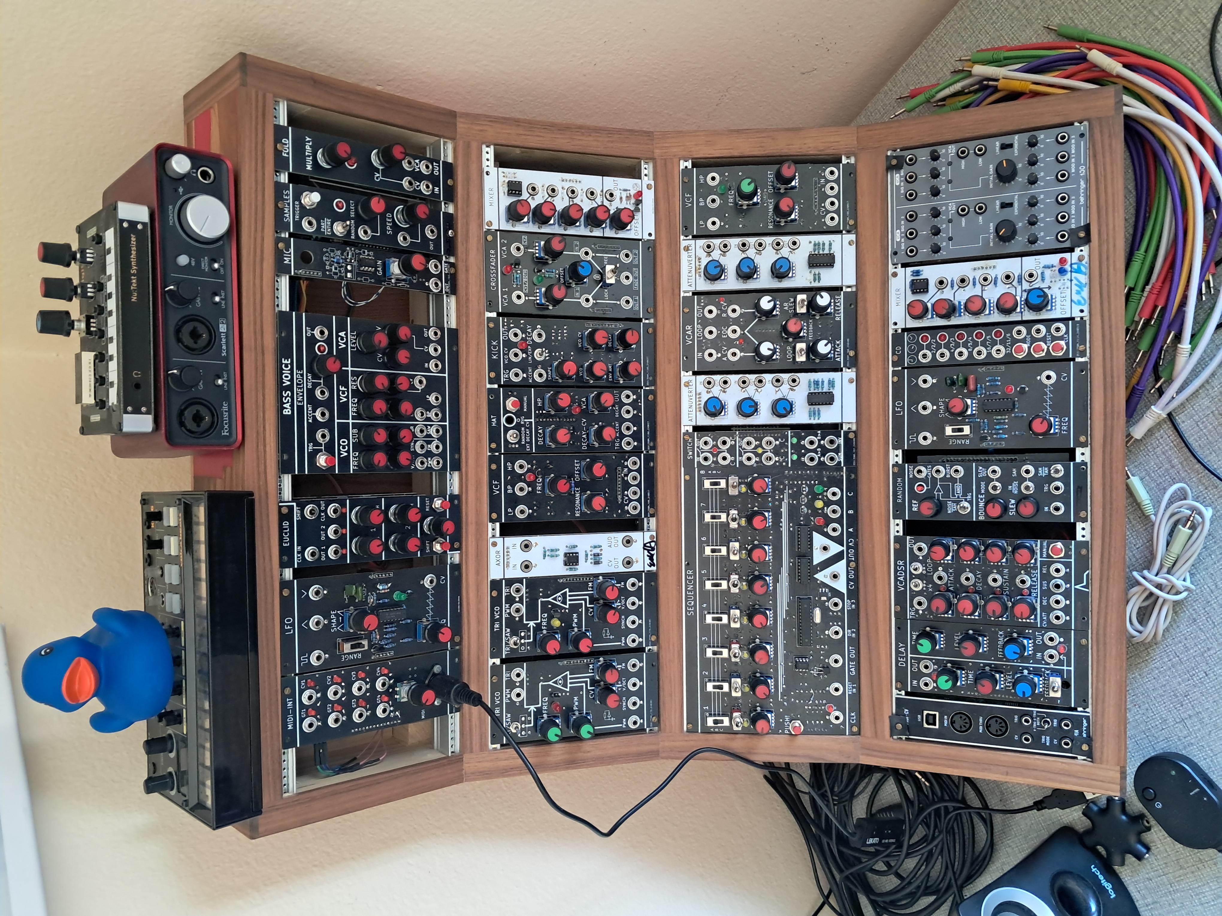
Update from 10.05.2025: The picture below shows my current setup, as you can see, many modules have solder joints on the front because I started out by making the frontplates out of PCB with the circuitry on them. All* of my proper modules have now been fixed in Kicad to be free of solder joints on the front but the image below will remain the same for a LONG time (I'm NOT soldering 15+ modules again to fix a minor issue lol)
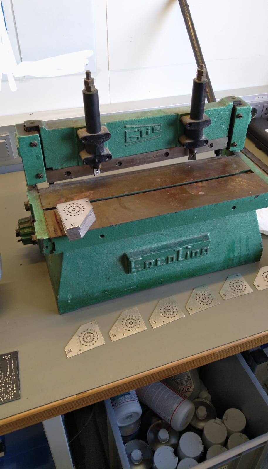
If you were to build these modules yourself make sure to separate the boards in the KiCad projects! Besides revision boards, I combine every PCB of a module into a single board (because its cheaper) and use a PCB cutter like this to separate them. Separate the boards in the KiCad project or add V-cuts.
Most modules have some minor bugs, they are summarised in the "README.md" of each module. Please inspect the Kicad projects before ordering.
Open points and Issues that can be applied to the whole project are summarized in "General_Issues.txt"
*Update 10.05.2025:
The frontplates of:
AXOR, Attenuverter, Bell, Crossfader, Clockdivider, Delay, Drum, Euclid, Fold, Hat, MIDI-INT, Mixer, RandomSource, SimpleSampler, Switch, TRIVCO, VCAR, VCF and Voice
are now free of solder joints. The modules that still have solder joints on the front will be updated or replaced with a better version in the future.